
A solar panel may look like a simple rectangular module, but there's a lot more to its design than what you see from the outside. Dimensions, cell arrangements, cable positions, mounting points, and electrical connections all affect how a panel fits into a real project.
That's why a drawing of solar panels is more than an engineering document. It gives buyers, designers, installers, and project managers a practical way to understand a solar product before manufacturing or installation begins.
Whether you're planning an RV solar system, a rooftop project, or a custom solar installation, knowing how to read these drawings can save time and prevent costly design changes.
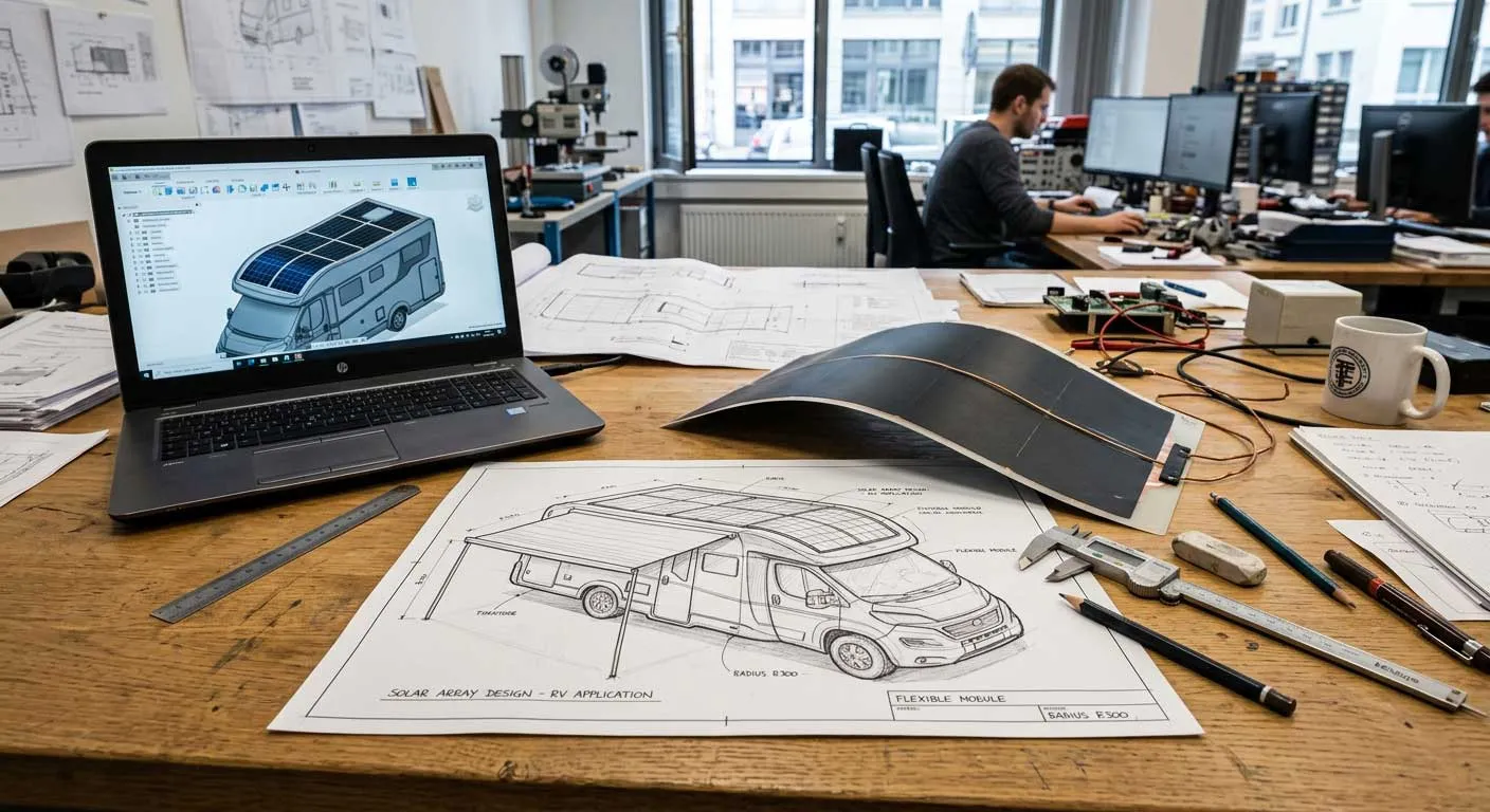
A basic product drawing may include:
For anyone purchasing solar panels in bulk, these details are worth reviewing before confirming an order.
Imagine installing solar panels on an RV roof. The roof may appear large enough at first, but once you account for air-conditioning units, skylights, vents, and roof racks, the usable area becomes much smaller.
A layout drawing helps determine how many modules can fit and where they should be positioned.
The same applies to boats, yachts, industrial equipment, and commercial rooftops. In these applications, the available surface may have an unusual shape or limited installation space.
When reviewing a layout, pay attention to:
Panel spacing: Leave sufficient clearance according to the mounting design and manufacturer's requirements.
Obstructions: Identify vents, equipment, hatches, and other objects that could interfere with installation or cause shading.
Cable routing: Make sure cable exits and connection points are accessible without creating unnecessary cable runs.
Installation access: Consider whether the panels can be inspected, cleaned, and maintained after installation.
A layout that works on a computer screen still needs to make sense on the actual installation surface.
For engineering teams and installers, dimensions are particularly important. A difference in module thickness, cable position, or mounting-hole spacing can affect the entire installation arrangement.
For example, a custom solar panel designed for a curved vehicle roof may need specific dimensions to fit around existing equipment. If the panel is manufactured using approximate measurements, it may not match the intended installation area.
Before approving a technical drawing, check the following:
A mechanical drawing explains the physical structure of a solar panel. A solar panel wiring diagram focuses on how electrical components connect.
Depending on the system, the diagram may show solar modules connected in series or parallel, together with charge controllers, batteries, inverters, and other equipment.
Here's the basic difference:
Series connection: Connecting panels in series increases the combined voltage while the current is limited by the string's operating characteristics.
Parallel connection: Connecting panels in parallel increases the available current while maintaining approximately the same operating voltage.
The correct arrangement depends on the electrical specifications of the modules and connected equipment.
Always check Vmp, Imp, Voc, and Isc before selecting a wiring configuration. The maximum voltage and current must remain within the limits of the inverter or charge controller.
A wiring diagram should be reviewed alongside the product datasheet, not treated as a replacement for it.
RV roofs, boat decks, curved surfaces, and specialized equipment can require different panel dimensions or layouts. This is where custom solar panel drawings become especially useful.
A custom drawing allows the project team to discuss product requirements before manufacturing begins.
For example, a marine solar project may require a particular module shape to fit the available deck space. An RV project may need a different cable exit position to simplify electrical routing.
When discussing a custom design with a supplier, prepare the following information:
However, a drawing alone cannot confirm product performance or installation suitability. Always review the corresponding datasheet and confirm any special requirements with the manufacturer.
One common mistake is checking only the overall dimensions while ignoring cable positions and mounting details. Another is using an outdated drawing after the product specification has changed.
It's also important not to confuse a conceptual layout with a manufacturing drawing. A visual mockup may communicate the general arrangement, but it may not contain enough information for production.
Before approving a drawing, check its revision number, dimensions, electrical references, and consistency with the latest product documentation.
If something is unclear, ask the manufacturer rather than making assumptions.
At Bright Solar, understanding the installation environment and product requirements is an important starting point for developing suitable solar solutions. Whether you're sourcing standard flexible solar panels or discussing a custom project, reviewing the technical drawing before production can help keep your project on the right track.
That's why a drawing of solar panels is more than an engineering document. It gives buyers, designers, installers, and project managers a practical way to understand a solar product before manufacturing or installation begins.
Whether you're planning an RV solar system, a rooftop project, or a custom solar installation, knowing how to read these drawings can save time and prevent costly design changes.
1. What Does a Drawing of Solar Panels Show?
A solar panel drawing is a visual representation of a module or solar array. Depending on its purpose, it can show the external appearance, dimensions, internal structure, mounting arrangement, or electrical configuration.A basic product drawing may include:
- Overall length, width, and thickness.
- Solar cell arrangement and module appearance.
- Junction box and cable positions.
- Connector locations and specifications.
- Mounting holes, grommets, or attachment points.
- Relevant structural and installation details.
For anyone purchasing solar panels in bulk, these details are worth reviewing before confirming an order.
2. Solar Panel Layout Drawing: Plan the Available Space
One of the most useful applications of a solar panel layout drawing is space planning.Imagine installing solar panels on an RV roof. The roof may appear large enough at first, but once you account for air-conditioning units, skylights, vents, and roof racks, the usable area becomes much smaller.
A layout drawing helps determine how many modules can fit and where they should be positioned.
The same applies to boats, yachts, industrial equipment, and commercial rooftops. In these applications, the available surface may have an unusual shape or limited installation space.
When reviewing a layout, pay attention to:
Panel spacing: Leave sufficient clearance according to the mounting design and manufacturer's requirements.
Obstructions: Identify vents, equipment, hatches, and other objects that could interfere with installation or cause shading.
Cable routing: Make sure cable exits and connection points are accessible without creating unnecessary cable runs.
Installation access: Consider whether the panels can be inspected, cleaned, and maintained after installation.
A layout that works on a computer screen still needs to make sense on the actual installation surface.
3. Solar Panel Technical Drawing: Why Dimensions Matter
A solar panel technical drawing provides more precise information than a general product image.For engineering teams and installers, dimensions are particularly important. A difference in module thickness, cable position, or mounting-hole spacing can affect the entire installation arrangement.
For example, a custom solar panel designed for a curved vehicle roof may need specific dimensions to fit around existing equipment. If the panel is manufactured using approximate measurements, it may not match the intended installation area.
Before approving a technical drawing, check the following:
- Are the overall module dimensions clearly marked?
- Is the thickness specified?
- Are mounting positions and distances accurate?
- Are cable exits located where the project requires them?
- Does the drawing match the latest product specification?
4. Solar Panel Wiring Diagram: Understand the Electrical Connections
A mechanical drawing and an electrical diagram serve different purposes.A mechanical drawing explains the physical structure of a solar panel. A solar panel wiring diagram focuses on how electrical components connect.
Depending on the system, the diagram may show solar modules connected in series or parallel, together with charge controllers, batteries, inverters, and other equipment.
Here's the basic difference:
Series connection: Connecting panels in series increases the combined voltage while the current is limited by the string's operating characteristics.
Parallel connection: Connecting panels in parallel increases the available current while maintaining approximately the same operating voltage.
The correct arrangement depends on the electrical specifications of the modules and connected equipment.
Always check Vmp, Imp, Voc, and Isc before selecting a wiring configuration. The maximum voltage and current must remain within the limits of the inverter or charge controller.
A wiring diagram should be reviewed alongside the product datasheet, not treated as a replacement for it.
5. Drawing of Solar Panels for Custom Applications
Standard solar panels are not always suitable for every installation.RV roofs, boat decks, curved surfaces, and specialized equipment can require different panel dimensions or layouts. This is where custom solar panel drawings become especially useful.
A custom drawing allows the project team to discuss product requirements before manufacturing begins.
For example, a marine solar project may require a particular module shape to fit the available deck space. An RV project may need a different cable exit position to simplify electrical routing.
When discussing a custom design with a supplier, prepare the following information:
- Installation surface dimensions.
- Required panel shape and module size.
- Expected power output and electrical requirements.
- Mounting preferences and installation restrictions.
- Cable and connector requirements.
However, a drawing alone cannot confirm product performance or installation suitability. Always review the corresponding datasheet and confirm any special requirements with the manufacturer.
6. Common Mistakes When Reading Solar Panel Drawings
Even experienced project teams can overlook small details during drawing approval.One common mistake is checking only the overall dimensions while ignoring cable positions and mounting details. Another is using an outdated drawing after the product specification has changed.
It's also important not to confuse a conceptual layout with a manufacturing drawing. A visual mockup may communicate the general arrangement, but it may not contain enough information for production.
Before approving a drawing, check its revision number, dimensions, electrical references, and consistency with the latest product documentation.
If something is unclear, ask the manufacturer rather than making assumptions.
Final Thoughts
A well-prepared drawing of solar panels makes solar projects easier to plan, review, and communicate. From module dimensions and electrical layouts to custom shapes and mounting details, every part of the drawing helps clarify what needs to happen before installation.At Bright Solar, understanding the installation environment and product requirements is an important starting point for developing suitable solar solutions. Whether you're sourcing standard flexible solar panels or discussing a custom project, reviewing the technical drawing before production can help keep your project on the right track.